FAQs
Why are some blocks annotative and some not, and how can I tell which ones are which?
Where possible we have included annotative blocks to control the size and scale at which objects are displayed in model space or a layout. Some blocks are required to display at true scale (such as manholes and wheelchair ramps) and as a result require non-annotative blocks. Also blocks such as title blocks, scale bars, etc., which reside in paper space, do not need to be annotative. All annotative blocks are named with an (Anno) suffix to differentiate them from non-annotative blocks.
When is it required to use the N or E suffixes to differentiate between new and existing features?
All layers that start with the discipline designator “V”, are implied to be existing features, and therefore do not require the “E” suffix. All other layers are implied to be design (i.e., new) features, unless otherwise specified, and therefore do not require the “N” suffix. However, when showing an existing feature that does not start with the “V” discipline designator, it is required to attach the “-E” suffix. For example, “A-DOOR-E” is an existing door, to differentiate from A-DOOR which is a proposed door to be placed at a location. Differentiating between an existing surveyed feature and a design one can be done by the discipline designator (e.g., V-ROAD vs C-ROAD).
Is there a way to reduce the number of layers in the templates so that the drawings do not get bloated?
The number of layers do not materially increase the size of drawings. However, having too many layers can make it time consuming and difficult to find the desired layer. To alleviate this, layer filters may be used to reduce the number of layers that a user will see at any given time.
What if I need a layer or a symbol for a feature on my drawing which does not exist in the standard?
If you need to create a new layer, you may do so as long as it follows the standard naming convention as described in the CAD Standard Guidance Document. Symbols may also be used which are not in the standard. Please send an email to CADinfo@calgary.ca to let us know that your drawing will be using new layers or symbols, and what they are (please attach a .dwg file showing the new blocks and/or the layers so we can see what colours/linetypes were used). This will allow us to consider including them in future revisions of the templates, either as submitted or by adjusting them.
Can I still use the old CAD Block Profile Standard layers and blocks?
No. The City’s Block Profile Standard has been updated to focus exclusively on the required content, with a reference to this Standard for the layers and symbols that must be used. The current Block Profile Standard is located in the ‘Technical and Design Specifications’ section in the Planning & Development resources library.
Will I be able to download reference files from City Online in the new standard?
Yes, reference files on City Online are now available in the new AutoCAD Standard.
Is the City switching to the GCV2013 vertical datum?
Not at this time. The City is using the 1928 GCVD28 version for now.
Is the standard mapping projection in grid or ground coordinates?
It is in grid coordinates, but linear dimensions must be annotated as ground level distances.
I’m getting an error message indicating a bad definition of a .LIN file.
This may occur if a user purges text styles from the template and then tries to load line types that depend on specific text styles. For example, many line types depend on the ‘NCS’ text style to display text within the line type. If that ‘NCS’ text style is purged from the template, users will receive an error message.
Which template do I use to create a Block Profile?
To create a block profile, you should use the Civil template (that has all the styles to be used for civil design features), the Survey and Mapping template (to create the XREFs), and the General template to import the “002 - GENERAL DESIGN - ANSI D (22x34) LANDSCAPE” layout. See the “Title Block” section in the Guidance document for instructions on how to import a title block into your template.
The new title block doesn’t have an area for additional consultant logos. Where can I put them, if required?
Additional consultant’s logos may be placed towards the bottom of the Notes section on the Title Block as shown here:
![]()
Is it acceptable to submit AutoCAD® 2022 drawings?
The City provides templates created in AutoCAD® 2018 but will accept files in any version from 2013 to 2022*.
*Note: The City currently does not have AutoCAD® 2022, so consultants may be required to save to a previous AutoCAD version if there is any data loss when opening 2022 files with the City’s previous AutoCAD® versions.
I’m having problems getting the hatches to display properly
There is a system variable, HPMAXLINES, that controls the number of hatch lines that are generated. If it set to too low of value, some hatches may disappear at certain scales. If you see this behaviour, increase the HPMAXLINES variable to 1 000 000 (or higher if it’s already at that value) and this problem should disappear.
Why do dimension lines above labels sometimes not extend to where they should?
The following Storm Profile Labels require that a reference alignment be applied to the pipe for the dimension line to extend to the start and end locations:
Is it possible to add a 3rd digit on the Sheet designator for block profile numbering as we may require more than 99 profiles?
The as-built block profile numbering is not changing as part of this standard. The Sheet Identification standard applies to contract set drawings. As-built block profiles do not include a sheet id, but just a profile number. You can see an example of a block profile drawing using the new standard, on our website here. You can see the profile number on the bottom right, and no sheet identification referenced on it.
Your standards have supplied a folder structure - are we required to use this structure?
The folder organization referenced in the CAD Standard Guidance document describes the standard that City of Calgary internal staff follow when creating and saving files. External consultants are not required to comply with this.
Can you explain what the ~ means in the folder names?
The tilde (~) is a place holder that the NCS uses. For example, in layer names, four characters are to be used for Major/Minor Group field codes. If you need to create a group name like TOP, because it only has three characters the tilde would be added to make up the fourth character: TOP~. The folder names have been created in this same manner.
The sample drawings don’t include everything that we’ve been asked to show on drawings in the past. What should be included in drawings prepared using the new CAD Standard?
The City’s CAD Standard specifies how features should be represented on drawings, but not what should be on these drawings. That content is specified in various design guidelines, as well as project specific requirement documents, and those are not changing as part of the new CAD Standard.
I can’t find any reference on the text sizes for different labels such as plan number, street names, lot number, profile text sizes, etc.
All of the Civil 3D styles for civil objects have predefined text styles/height, so once the styles are applied to the objects (profile labels for example), the proper styles/heights will be used. For other labels, as a general guideline, most text for existing features should use the “Existing 1.8 Anno” style (see Existing Dimensions , Text, and MultiLeader Styles), and text for design features should use the “Proposed 2.0 Anno” style (see Proposed Dimensions , Text, and MultiLeader Styles) (which are 1.8 and 2.0 mm heights respectively). Note there are other styles available to support flexibility in cartographic representation. Some text is provided in larger sizes in our reference files to provide emphasis, such as block numbers 3.5 mm and plan number 2.5 mm.
Is it possible to get access to the CAD files for the sample drawings?
No, we’ve decided not to provide CAD files for the sample drawings. The reason for this is that there would be a lot of overhead in keeping the samples fully compliant (in terms of block names, layer names, etc.) as the Standard is refined over time, and providing non-compliant samples would be confusing. We do, however, provide annotated PDFs for some of the sample drawings, which help identify standard text styles, layers, blocks, etc.
Can we submit eTransmit drawings for block profiles?
Currently we will continue to require exported-2D drawings for block profiles. We are, however, revisiting our drawing submission and processing processes, and will likely accept either exported-2D drawings or eTransmit drawings in the future.
Why does text sometimes appear as comments on a PDF?
This is related to the usage of the RomanS font in our template, and a feature in AutoCAD to allow for searchable text in a PDF when SHX fonts were used in the DWG file. To fix this, on the command line in AutoCAD enter EPDFSHX and change the value to 0. See here for more details.
How do I use the City’s template which was created in AutoCAD 2015 in my 2018 version of the software?
You may simply open it up in the 2018 version and it will work without any additional steps.
Is there a way I can label ground coordinates with grid values?
Label styles with ‘Ground to Grid’ in the name will apply a scale factor to a feature stored in ground coordinates to display its grid coordinates.
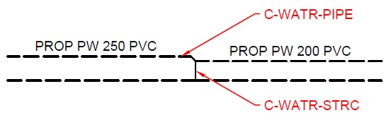
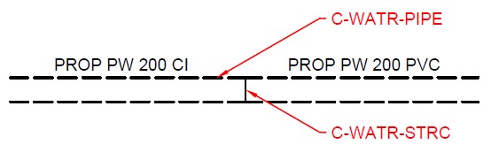
How should a material change or a change in pipe size for waterlines be represented in a profile?
As shown in the following screen shots, the City of Calgary preferred approach is to:
- draw a vertical line for couplings, and
- draw a vertical line and a 45 degree line for reducers.
The CAD Standard templates don’t have a place to put the Microfilm Number. Where should this be recorded in drawing packages?
The City is now referring to the old ‘Microfilm Number’ as an ‘Engineering Drawing Number’, so it should go in the ‘Engineering Drawing Number’ field in the title blocks and cover sheets.
Disclaimer: The City of Calgary (the "City") CAD standards and provided tools are intended for information purposes only. No warranty or representation as to the completeness or accuracy of said materials is made. The Contents on this Site and its compilation is protected by Canadian and international copyright, and trademark laws. The City acknowledges that the CAD Standards were developed by adopting and amending the Master Municipal Construction Documents Association (MMCD) Standard, and supplemented with additional information from the National CAD Standard (NCS). Copyright materials from both organizations incorporated within the City’s CAD Standards is owned by the respective organization. For more information on using the content on this site, please see the City of Calgary Terms of Use.